(Technology Preview) To Create a Solid with Guide Wires
-
Select the
Loft Solid tool.

-
In the tool settings, click
Loft by Sections with Guide Wires.

- Select a guide wire.
- (オプション) Select more guide wires.
- Enter a data point.
- Select the first profile.
- Select additional profiles.
- (オプション) Modify the profiles. The direction of the red arrow can be changed and the location can be moved by dragging the rotation ball.
-
Enter a data point.
The solid displays.
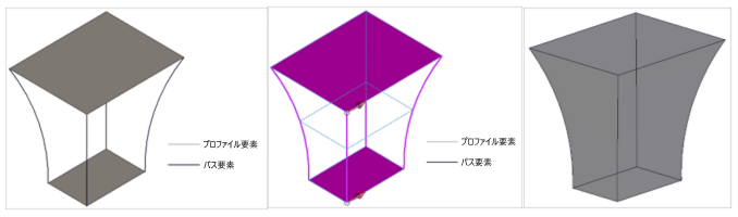
注記: To obtain the
desired curve, the location of a Start Point for each profile element must be
identical. You can drag the rotation ball attached to the start of the
direction arrow during the preview state if needed. Every element's profile
curve must follow the same curve direction. The curve direction can be toggled
by using a Data point. To generate accurate lofted solids, it is recommended to
have the desired profile element at the respective node of the path elements,
as shown in the image below:
